1. Foreword
This specification is an extension of the released drawing of the affected parts. All requirements of this specification must be met, in addition to all other requirements of the part drawing. The part drawing will always supersede the specification requirements.
The engineering tests and values contained within this specification reflect minimum values established to provide conformation of design intent. The frequency of the tests, dimensional checking, in-process controls should be agreed upon between TRW Engineering, supplier quality and should be documented in the mutually agreed upon supplier control plan.
The function of the casting is to contain the electro-mechanical components that provide a directional control mechanism for vehicle steering.
2. Purpose
The purpose of this specification is to designate TRW requirements for aluminum casting components, specifically rack and pinion housings and other cast housing designs used in MSG (mechanical), HPS (hydraulic) and EPHS (electrical hydraulic) and EPS (electrical) Belt Drive steering gear applications.
3. Scope
This global specification is applicable to high pressure die casting aluminum components to be used for MSG, HPS, EPHS, EPS steering gears. It defines mechanical properties, porosity and other requirements of the castings.
3. Reference Documents
|
Drawing . # |
Doc. # |
Title |
Place of location |
|
1 |
ASTM E 505 |
Standard reference radiographs for inspection of aluminum and magnesium die casting (pressure die casting) |
TCDweb |
|
2 |
DIN 1688-1 |
Casting tolerances for sand die casting |
TCDweb |
|
3 |
DIN 1688-3 |
Casting tolerances for gravity die casting |
TCDweb |
|
4 |
DIN 1688-4 |
Casting tolerances for pressure die casting |
TCDweb |
|
5 |
DIN EN 12 |
Founding – Radiographic examination |
TCDweb |
|
6 |
DIN EN 444 |
Non-destructive testing; general principles for the radiographic examination of metallic materials using X-rays and gamma-rays |
TCDweb |
|
7 |
DIN EN 462 – 1 |
Non destructive testing – Image quality of radiographs |
TCDweb |
|
8 |
DIN EN 473 |
Non destructive testing – Qualification and Certification of NDT personnel- General principles |
TCDweb |
|
9 |
DIN EN ISO 10049 |
Aluminum Alloy Casting – Visual Method for Assessing |
TCDweb |
|
10 |
DIN ISO 13715 |
Edges of undefined shape (Vocabulary and indications) |
TCDweb |
|
11 |
ISO 8062 |
Castings – Systems of dimensional tolerances and machining allowances |
TCDweb |
|
12 |
ISO 8062-1 |
Geometrical product specifications (GPS) – Dimensional and geometrical tolerances for molded parts – Vocabulary |
TCDweb |
|
13 |
ISO 8062-3 |
Geometrical product specifications (GPS) – Dimensional and geometrical tolerances for molded parts – General dimensional and geometrical tolerances and machining allowances for castings |
TCDweb |
|
14 |
JIS B 0403 CT6 |
Casting tolerances for pressure die casting |
TCDweb |
|
15 |
TRW 31845101 |
Casting tolerances |
PDM |
|
16 |
TRW 62005004 |
Anodic Oxidation for Al casting |
PDM |
|
17 |
TRW 62045004 |
Contamination of components and assemblies of hydraulic systems, definition and classification |
PDM |
|
18 |
TRW 62050001 |
Design Verification and Product Validation of Rack and Pinion steering gears and Steering systems, Test program overview |
PDM |
|
19 |
TRW 81000068 |
Resin Sealer (Europe) |
PDM |
|
20 |
TRW S0000266 |
Leakage test (Europe) |
PDM |
|
21 |
TRW S0000121 |
Resin Sealer (NA) |
PDM |
|
22 |
TRW S0000120 |
Leakage test (NA) |
PDM |
|
23 |
TRW S0000822 |
Leakage test (AP) |
PDM |
|
24 |
VDA 1 |
Quality Management in the Automobile Industry, Quality Evidence |
TCDweb |
|
25 |
VDA 2 |
Quality Management in Automotive Industry, Safeguard Quality of Suppliers |
TCDweb |
|
26 |
VDG P210 |
Volume deficits on castings in non-ferrous metal |
TCDweb |
4. Dimensional Properties
TRW recommends the use of a computerized coordinate measurement machine (CCMM) for evaluation of appropriate dimensions. The CCMM Type shall be the standard by which supplier gauging is measured. TRW recommends that suppliers fabricate CCMM fixtures similar in function to TRW MSG, HPS, EPHS or EPS production plants for the purpose of measurement correlation. A common design CCMM fixture should be agreed with TRW quality. Short term capability shall be evaluated statistically by the supplier. (Refer engineering drawing for specific requirements.)
5. Mechanical Tests
Mechanical test conduction shall be agreed between TRW quality, TRW product engineering and supplier. If the test is conducted by the supplier the complete documentation including test results, setup photographs, and post test data has to be distributed to TRW quality and Product engineering for approval.
5.1 Component Pulser Test (optional)
In order to compare the fatigue strength of the foot mount of different housing versions as well the structure, position and characteristic of the breakage this Pulser test can be performed during running production or as serial accompanying test.
Further if the fatigue of the foot mounts is adequately addressed within the TRW testing scope for the production release of the gear, this comparative test can be performed optionally when changes are to be implemented from the serial process in terms of cast process, material and heat treatment of the housing Test as performed by TRW as shown in Figure 1. The housing has to be constrained to prevent rotation or movement.

Figure 1
Test is to be conducted without rubber bushing or foot insert in order to have better crack detection and shut-off criterion and higher testing frequency.
Unless otherwise specified the following parameters should be used:
Load: (1/m) x 0.9 x Fn
Frequency: 10-50 Hz
Cycles: > 150000
Specimen: > 6
Fn = max. rack load
m = number of foot mounts
5.2 Component Bend Strength Test (optional).
In order to compare the fatigue strength of different housing batches (e.g. different supplier, mold changes
etc.) the bend test may be performed as shown in the following figures.
General test procedure:
• Mount casting housing in test fixture supporting the ends and rack bore as shown in Figures 2.1-
2.8. (Figures shown below are for schematic purpose only. Refer product drawing for actual
geometry.)
The length of the supports should be 15mm ± 2.0 mm. The centre of the housing is where the
load should be applied if applicable. If there is a casting feature which prohibits applying load to
the center it is then allowable to move the pusher to a different position, but this position has to be
agreed with the TRW Engineering and the supplier.
• Orient the housing as determined by TRW Engineering and vehicle configuration. Extra fixturing
may be used to maintain the pinion housing axis in the respective plane. However, the extra
fixturing shall not bias the test results.
• Apply a load at the rate of 12.7mm ± 0.25mm per minute. Do not restrict lateral movement of
housing during test. Load applicator to have a radius of 6.35 mm.
Housing Bending Load Requirement:
The bending load requirement shall be designated on the drawing if applicable.
Use Table 1 for new projects as a starting reference point in absence of any customer or internal
requirements.
TABLE 1: REFERENCE PINION HOUSING BEND TEST REQUIREMENTS
| Pinion Housing Bend Strength Test Reference Table Minimum Fracture L .oad | |||
| Rack diameter [mm] | Housing design | Load applicator [mm] | Min. Fracture load [kN, (lbs)] |
| 24/25 | Short Hsg D-mount, inside, out side | R6.35 | 15.0 (3300) 14.0 (3100) 15.0 (3300) |
| Long Hsg. HPS | 8.0(1700) | ||
| Long Hsg. EPS | 11.12 (2500) | ||
| 28 | Short Hsg D-mount, inside, out side | R6.35 | 15.0 (3300) 14.0 (3100) 15.0 (3300) |
| Long Hsg. HPS | 8.0(1700) | ||
| Long Hsg. EPS | 11.12 (2500) | ||
| 32 | Short Hsg D-mount, inside, out side | R6.35 | 16.0 (3300) 14.0 (3100) 16.0 (3300) |
| Long Hsg. HPS | 8.0(1700) | ||
| Long Hsg. EPS | 11.12 (2500) | ||
5.2.1 Foot mount (inside) housing

Figure 2.1
Requirements: See pinion housing print or Table 1.
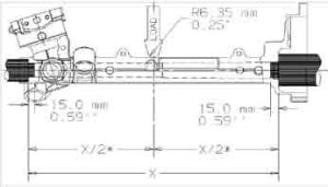
Figure 2.2
Requirements: See pinion housing print or Table 1.
5.2.2 D-mount housing
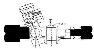
Figure 2.3
Requirements: See pinion housing print or Table 1.
5.2.3 Foot mount (outside) housing
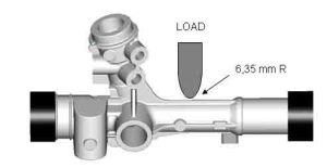
Figure 2.4
Requirements: See pinion housing print or Table 1.
5.2.4 Foot mount housing (split housing design)
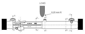
Figure 2.5
Requirements: See pinion housing print or Table 1.
The following three photographs show pinion housing bend setup currently used at TRW Washington, MIfacility (see Figure 2.6 to 2.8).
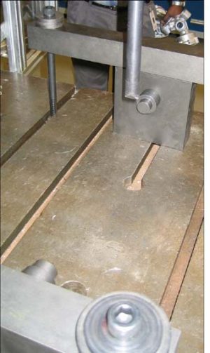
Figure 2.6

Figure 2.7

Figure 2.8
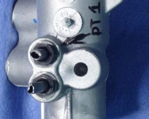
5.3 Ports Torque To Failure Test For HPS And EPHS (optional)
A pinion valve housing typically contains at least 4 ports, two internal pressure ports which are commonly referred to as transfer ports as they help transfer fluid to the correct side of the cylinder which provides hydraulic assist while steering. The remaining two ports are typically the external pressure ports commonly referred to as the supply (or pressure) and return ports (see Figure 3 for tested part). These are the inlet to and outlet from the steering gear that are connected to the hydraulic pump and reservoir respectively. These sizes though common are not always standard as flow requirements dictate the various sizes.
The internal and external pressure port design depends on system and customer requirements. Port design has to be defined by Product engineering and OEM. The minimum accepted torque must be
defined by product engineering.
During PPAP these ports on a machined housing shall be torqued to failure per procedure prescribed below.
(1) Torque the lower internal pressure port first to failure and record torque to failure using a calibrated static torque wrench.
(2) While torquing this port the flared tube, an un-deformed Teflon ring (if used) and the fitting shall be used. The flared tube and the fitting should not be used more than two times for the test. The max torque before either threads stripping or port breakage shall be communicated through a signed report to TRW. The report should include failure mode for each test. Sample photographs should also be provided. The assembly torque for these ports depends on the customer requirement.
Hence, failure torque should be statistically (mean minus 3 sigma and min range) above defined torque.
(3) Next the upper internal pressure port should be torqued to failure as outlined through points 1 and 2.
The only difference in this case is that the lower port should be torqued to the defined max. Torque before the upper port is torqued to failure. The acceptance criteria for the lower port and upper port are identical.
(4) Next the pressure line should be torqued to failure. If the internal pressure ports are in the same cluster then both these ports should be torqued to defined torque before the test. If the port is not in the same cluster as the internal pressure ports then it may be torqued to failure independently.
Reuse of fittings is permissible up to two times. Acceptable parts are those that show are statistically capable to the defined torque requirements. Torque depends on customer requirements.
(5) The last step is to torque test the return port to failure. If the supply port is in the same cluster as the return port then the supply port fitting assembly should be torqued to defined torque before torquing the return line. Reporting for the pressure and return port failure modes should be similar to that specified for the internal pressure ports.
5.4 Foot Mount Shear Test (optional)
