Zinc Electroplating On Ferrous Materials
-
SCOPE
1.1 This specification defines the requirements of electroplated zinc deposited directly on a ferrous substrate. Provisions for plating thickness and neutral salt spray corrosion resistance are included. Hot dip galvanizing, zinc spraying or the replacement of zinc with cadmium are not allowed per this specification.
1.2 This specification may involve hazardous materials, procedures and apparatus. This specification does not address the health and safety problems associated with its application or use. It is the specification user’s responsibility to follow appropriate health or safety practices and determine the application or regulatory limitation prior to use.
-
APPLICATION
This specification was released to define performance requirements for zinc electroplating where corrosion protection on ferrous surfaces are required.
-
DESIGNATION
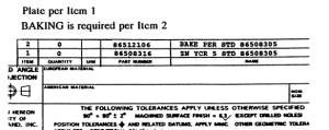
The Engineering drawing or standard shall contain the following notation for the specification of zinc electroplating. Notion shall appear as noted below and in Figure 1.
Plate per item (X) where (X) is the item number
BAKING is required per item (X)
The baking requirement shall be noted on Engineering drawings for parts having hardness greater than 34 Rockwell C or that are severely cold worked.
In addition to the above requirements, the plating specification shall be noted above the title block as shown in Figure 1. The part number shall be taken from Table 1. This number shall be matched with the numbers in Table 3 and the matching name will be used in the item name block as seen in Figure 1. The quantity shall be “0”.
86508316 (FNHA-2-H-500.25) is the Zinc Electroplating Specification used most often for hardware.
FIGURE 1
3.1 The dimensions specified on the drawing are before plating. If the application does not allow the additional thickness of plating, the actual required limits must be specified on the drawing and noted “AFTER PLATING”.
-
RELATED STANDARDS
ASTM B117—Standard Method of Salt Spray (Fog) Testing
ASTM B183—Practice for Preparation of Low Carbon Steel for Electroplating
ASTM B201—Practice for Testing Chromate Coatings on Zinc and Cadmium Surfaces
ASTM B 242—Practice for Preparation of High Carbon Steel for Electroplating
ASTM B320—Practice for Preparation of Iron Castings for Electroplating
ASTM B487—Method for Measurement of Metal and Oxide Coating Thickness by Microscopical Examination of a Cross Section
ASTM B571—Test Methods for Adhesion of Metallic Coatings
-
REQUIREMENTS
5.1 CLASSIFICATION
This specification provides a selection from four (4) zinc electroplating thickness with a combination of three (3) passivating treatments. Also, this specification makes a provision for a wax coating to be applied to improve the frictional characteristics of the plated surface.
5.2 DESCRIPTION
5.2.1 Specifications 86508307 through 86508310 (FNHA-2-H500.00 through .09): These specifications will consist of a zinc electroplate without a passivation treatment. This electroplating appearance is bright silvery and will exhibit the least corrosion resistance. This process is also the least expensive.
5.2.2 Specifications 86508311 through 86508314 (FNHA-2-H500.10 through .19): These specifications will consist of a zinc electroplate and a passivation treatment by a clear or a colored chromate treatment
leached clear. The appearance is a bright silvery or light blue hue. The corrosion resistance is considered to be intermediate.
5.2.3 Specifications 86508315 through 86508322 (FNHA-2-H500.20 through .39): These specifications will consist of a zinc electroplate and a passivation treatment by a chromate coating. The 86508315 through 86508318 (FNHA-2-H500.21 through .29) appearance is yellow to brown including olive drab. The corrosion resistance is considered to be the greatest. 86508319 through 86508322 (FNHA-2-H500.31 through .39) appearance is black. This black coloring of the chromate tends to reduce this coating’s resistance to corrosion.
5.2.4 Specifications 86508323 through 86508338 (FNHA-2-H500.50 through .99): These specifications will consist of the same as above mentioned specification categories with the addition of a wax finish to alter the surface coefficient of friction.
5.3 SURFACE PREPARATION
Prior to electroplating, the parts shall be thoroughly cleaned and free from rust, scale, oil or any other foreign matter which would be detrimental to the finish or adhesion of the plating. Particular care should be taken in the cleaning operation to prevent hydrogen embrittlement of parts exposed to high stress in service, prior heat treatment or cold working. It is recommended that the appropriate practices be used: ASTM B183, ASTM B242, ASTM B320.
5.4 ELECTROPLATING THICKNESS
5.4.1 Component Parts
The electroplating thickness shall be not less than the thickness specified in Table 1 for the specific classes. This coating thickness shall be applied only to significant surfaces. Other non-significant surfaces shall have a minimum of the next lowest class thickness with respect to the selected class. When Class 3 thickness is selected, the non-significant surfaces shall have a minimum of 1/2 the minimum thickness.
5.4.2 Definition
Significant Surface: Surface which is visible, susceptible to corrosion, and on which electroplating is a necessary function, unless otherwise specified on Engineering drawings or standards. In general, the portion of the visible surface on the part which can be touched by a 20 mm (0.75 inch) diameter sphere. Sharp edges are excluded.
5.4.3 Maximum Electroplating Thickness for Threads on Fasteners
The maximum allowable thickness of zinc electroplating applied to the threaded surface is described on Table 2. The location of this thickness shall be measured at 1 diameter from the threaded end of the fastener and at 1/2 the tooth height of the thread. This maximum thickness may be altered if the manufacturer of the threaded fastener takes into account the changes in pitch diameter due to the electroplating and can assure there is an allowance maintained within standard threaded manufacturing practice after electroplating. This shall be negotiated with Purchasing Plant and Materials Engineering activity prior to submittal of samples. Internal threaded component parts having a hole depth greater than 6mm (0.25 inches) need not meet the requirements on the threaded portion unless otherwise specified on the Engineering drawing or standard. When the fasteners are assembled, both the external and internal threaded component must run freely in its intended use.
5.5 CORROSION RESISTANCE
For all classes, the zinc electroplating on all significant surfaces except for sharp edges shall be capable of withstanding the neutral salt spray testing for the minimum number of hours specified in Table 1.
5.6 ADHESION
For all classes, the zinc electroplating shall be sufficiently adherent to the substrate to pass the selected adhesion tests described in the methods of testing.
5.7 HYDROGEN EMBRITTLEMENT
Baking Process 86512106
All steel casting parts having a hardness above 34 Rockwell C or 313 Brinell hardness plus all parts highly stressed in service and all parts severely cold worked and subsequently plated can become embrittled due to the absorption of hydrogen. These parts shall be baked to relieve this condition immediately after plating, unless otherwise specified on the Engineering drawing or standard. The baking process shall consist of heating the parts in an oven to 175°C (350°F) for at least 4 hours at temperature. For hardened parts where tempering temperature is below 175°C (350°F), the baking shall be done at 150°C (300°F) for at least 8 hours at temperature. The baking operation shall be done prior to any supplementary treatment. Engineering shall note “Baking is required” on their drawings when their parts have a hardness greater than 34 Rockwell C or when their material has been severely cold worked.
5.8 QUALITY
The zinc electroplating shall be fine grained, smooth, adherent, and free from pits, nodules, blisters, indications of burning, and other defects. All detailing of workmanship shall conform to the best practice for high quality plating.
-
METHODS OF TEST
6.1 ELECTROPLATING THICKNESS
The minimum values for electroplating thicknesses are listed in Table 1. The maximum values for electroplating thicknesses for the threaded areas of fasteners are listed in Table 2. In cases of disputes, the plating thickness measurements shall be metallographic sectioning as per ASTM B487.
6.2 ACCELERATED CORROSION RESISTANCE (NEUTRAL SALT SPRAY)
The neutral salt spray test will be performed per ASTM B117. The minimum time requirements for the occurrence of corrosion product will be dictated in Table 1 for specific class selections. The evaluation shall be performed on only significant surfaces unless otherwise specified on the Engineering drawing or standard. The plating shall show no corrosion product (white or red) visible to the unaided eye at normal reading distance for the minimum specified times.
6.3 PASSIVATION TREATMENT
The determination of the presence of clear chromate coatings shall be done according to ASTM B201. The determination of the presence of color chromate coatings will be performed by visual observations.
6.4 ELECTROPLATING ADHESION
The adhesion of the electroplating must conform to the requirements of the test methods per ASTM B571 unless otherwise stated on the Engineering drawings or standard.
- Grind-Saw Test
No peeling or lifting of the subject electroplating from the substrate is permitted following the grind-saw test.
2. Burnishing Test
No peeling, lifting, or blistering of the subject electroplating from the substrate is permitted following the burnishing test.
6.5 HYDROGEN EMBRITTLEMENT TEST
6.5.1 Component Parts
Component parts which meet the requirements of being embrittled shall be tested. A random selection of at least 6 samples will be made and subjected to a load corresponding to its intended usage load or a minimum of 85% of its yield strength. This load shall be maintained for a minimum of 48 hours. Fracture of test parts is not acceptable.
6.5.2 Threaded Fasteners
Threaded fasteners which meet the requirements of being embrittled shall be tested. A random selection of at least 6 fasteners shall be subjected to a load of 85% of the minimum torque to fail the bolt by yielding. The test fixture shall consist of a plate with a hole for the fastener which has a one millimeter step to load one side of the head of the fastener. (See Figure 2.) The assembly shall be in the tightened condition for a period of at least 48 hours. Fracture of fastener is not acceptable.
The minimum torque to fail the bolt by yielding shall be the minimum torque value from tests performed on at least 3 fasteners.
FIGURE. 2: Hydrogen Embrittlement Test Fixture
-
SUPPLIER RESPONSIBILITY
7.1 Suppliers shall perform the necessary tests for sample approval for initial lots. After this approval suppliers are not required to perform the specific tests, but to ascertain that their product will conform to the specification limits. These specified requirements will be used to reconcile any disputed values.
7.2 All materials supplied to this specification shall be equivalent in all characteristics to the material upon which approval was originally granted. Prior to the making of any changes in the properties, composition, construction, color, dimensions, processing or labeling of the material originally approved under this specification, the supplier shall notify Purchasing and the affected Materials Engineering activity of the proposed changes and obtain the written acknowledgement of the Material Engineering activity. Test data, test samples, and a new identification code are to be submitted with the request.
TABLE 1
| ZINC ELECTROPLATED—MINIMUM REQUIREMENTS, NOT WAXED | ||||||
| Specification
FNHA-2-H-500. |
Part Number | Min. Plating Thickness on Significant Surfaces | Supplemental Treatment | Typical Appearance | Corrosion Resistance (Hrs) | |
| UM (Inches) | Base Metal Red | Zinc Plate White | ||||
| .03
.05 .08 .09 |
86508307
86508308 86508309 86508310 |
3 (0.0001)
5 (0.0002) 8 (0.0003) 13 (0.0005) |
NO REQUIREMENT | NO REQUIREMENT | 24
44 68 98 |
—
— — — |
| .13
.15 .18 .19 |
86508311
86508312 86508313 86508314 |
3 (0.0001)
5 (0.0002) 8 (0.0003) 13 (0.0005) |
PASSIVATION OR CONVERSION COATING | CLEAR OR LIGHT IRID BLUE | 32
54 94 120 |
8
8 8 8 |
| .23
.25 .28 .29 |
86508315
86508316 86508317 86508318 |
3 (0.0001)
5 (0.0002) 8 (0.0003) 13 (0.0005) |
YELLOW OR BROWN | 90
110 140 170 |
72
72 72 72 |
|
| .33
.35 .38 .39 |
86508319
86508320 86508321 86508322 |
3 (0.0001)
5 (0.0002) 8 (0.0003) 13 (0.0005) |
BLACK | 45
64 110 150 |
42
42 42 42 |
|
| ZINC ELECTROPLATED—MINIMUM REQUIREMENTS, WAXED | ||||||
| Specification
FNHA-2-H-500. |
Part Number | Min. Plating Thickness on Significant Surfaces | Supplemental Treatment | Typical Appearance | Corrosion Resistance (Hrs) | |
| UM (INCHES) | Base Metal Red | Zinc Plate White | ||||
| .53
.55 .58 .59 |
86508323
86508324 86508325 86508326 |
3 (0.0001)
5 (0.0002) 8 (0.0003) 13 (0.0005) |
NO REQUIREMENT | NO REQUIREMENT
|
24
44 68 98 |
—
— — — |
| .63
.65 .68 .69 |
86508327
86508328 86508329 86508330 |
3 (0.0001)
5 (0.0002) 8 (0.0003) 13 (0.0005) |
PASSIVATION OR CONVERSION COATING | CLEAR OR LIGHT IRID BLUE | 32
54 94 120 |
8
8 8 8 |
| .73
.75 .78 .79 |
86508331
86508332 86508333 86508334 |
3 (0.0001)
5 (0.0002) 8 (0.0003) 13 (0.0005) |
YELLOW OR BROWN | 90
110 140 170 |
72
72 72 72 |
|
| .83
.85 .88 .89 |
86508335
86508336 86508337 86508338 |
3 (0.0001)
5 (0.0002) 8 (0.0003) 13 (0.0005) |
BLACK | 45
64 110 150 |
42
42 42 42 |
|
MATERIALS / COATINGSFNHA-2-H-500.00
STD ZINC ELECTROPLATE86508305NE
TABLE 2
| MAX. ALLOWABLE ELECTROPLATED THICKNESS FOR THE THREADED AREAS OF FASTENERS | |||
| Metric | Threads/Inch | Maximum Thickness | |
| UNC | UNF | UM (INCHES) | |
| 48-44 | 4 (0.00015) | ||
| M2-M4 | 32 | 40-32 | 5 (0.0002) |
| M5-M8 | 24-20 | 28-24 | 6(0.00025) |
| M10-M12 | 18-16 | 20 | 8 (0.0003) |
| M16 | 14-13 | 18-16 | 9 (0.00035) |
| M20 | 12-11 | 10 (0.0004) | |
| M24 | 10-9 | 12 | 11 (0.00045) |
| M30 | 13 (0.0005) | ||
TABLE 3
| PART NUMBER | DESCRIPTION |
| 86508307 | ZN 3 STD 86508305 |
| 86508308 | ZN 5 STD 86508305 |
| 86508309 | ZN 8 STD 86508305 |
| 86508310 | ZN 13 STD 86508305 |
| 86508311 | ZN CCR 3 STD 86508305 |
| 86508312 | ZN CCR 5 STD 86508305 |
| 86508313 | ZN CCR 8 STD 86508305 |
| 86508314 | ZN CCR 13 STD 86508305 |
| 86508315 | ZN YCR 3 STD 86508305 |
| 86508316 | ZN YCR 5 STD 86508305 |
| 86508317 | ZN YCR 8 STD 86508305 |
| 86508318 | ZN YCR 13 STD 86508305 |
| 86508319 | ZN BCR 3 STD 86508305 |
| 86508320 | ZN BCR 5 STD 86508305 |
| 86508321 | ZN BCR 8 STD 86508305 |
| 86508322 | ZN BCR 13 STD 86508305 |
| 86508323 | ZN 3 W STD 86508305 |
| 86508324 | ZN 5 W STD 86508305 |
| 86508325 | ZN 8 W STD 86508305 |
| 86508326 | ZN 13 W STD 86508305 |
| 86508327 | ZN CCR 3 W STD 86508305 |
| 86508328 | ZN CCR 5 W STD 86508305 |
| 86508329 | ZN CCR 8 W STD 86508305 |
| 86508330 | ZN CCR 13 W STD 86508305 |
| 86508331 | ZN YCR 3 W STD 86508305 |
| 86508332 | ZN YCR 5 W STD 86508305 |
| 86508333 | ZN YCR 8 W STD 86508305 |
| 86508334 | ZN YCR 13 W STD 86508305 |
| 86508335 | ZN BCR 3 W STD 86508305 |
| 86508336 | ZN BCR 5 W STD 86508305 |
| 86508337 | ZN BCR 8 W STD 86508305 |
| 86508338 | ZN BCR 13 W STD 86508305 |
| 86512106 | BAKE PER STD 86508305 |