Impeller casting

An impeller is a rotating component used to increase the pressure, flow rate, or velocity of fluid. It is typically a wheel or rotor with vanes or blades that rotate inside a casing, creating a force that propels the fluid forward. Impellers are used in a wide range of applications, including pumps, turbines, and compressors, and are designed to provide optimal performance based on the specific requirements of the system. Our investment casting foundry is a China impeller investment casting manufacturer and supplier.

Vacuum pump impeller

Vacuum pump impeller

water pump impeller

Water pump impeller

pump stainless steel impeller

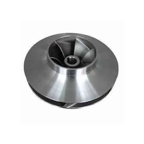
Pump stainless steel impeller
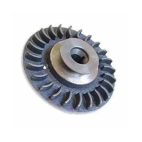
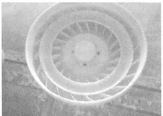
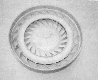
Fan wheel impeller

Fan wheel impeller

circulation body impeller

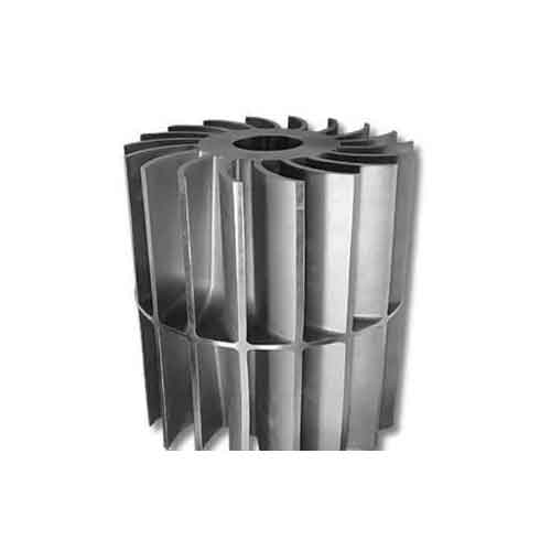
Circulation body impeller

custom made impeller for pump

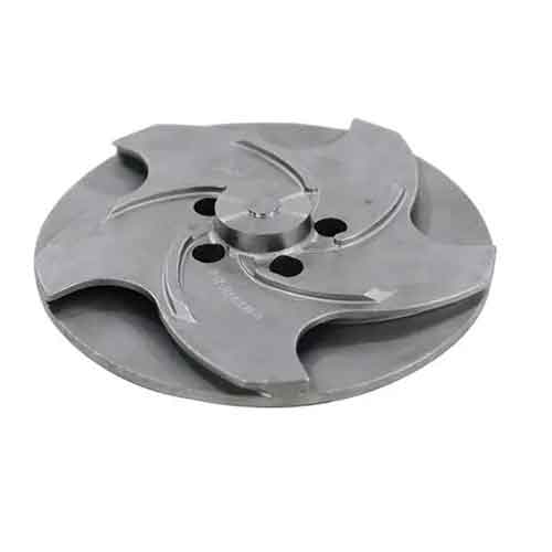
Custom made impeller for pump

 
Save Your Time?
Send us your requests directly

The manufacturing methods of the impeller

The manufacturing of an impeller can extensively vary depending on its application and its type. There are different manufacturing methods used for impellers, including:

Sand Casting, Investment Casting, Machining, Powder Metallurgy, 3D Printing…

  Among them, investment casting impellers are most welcomed. Investment casting allows for the production of intricate designs with thin walls and internal cavities that are difficult to achieve using other methods. Investment casting yields highly accurate and consistent castings with minimal finishing required.

We are a renowned supplier and manufacturer of Investment Casting-lost wax casting Impellers based in China. Our foundry specializes in creating investment casting impellers using 316L stainless steel or higher grades.

These impellers can be customized to suit the customer’s requirements by offering passivation, electropolishing, or mirror polishing. Our team can create mixing impellers as per the customer’s sample or drawing.

We have had successful exports of Investment Casting Impellers to several countries including Japan, USA, and Australia.

We welcome any inquiries regarding Investment Casting Impellers, so feel free to contact us.

Types of impeller

The optimal performance of a centrifugal pump is largely dependent upon its impeller design. An effectively designed impeller aims to enhance flow, reduce turbulence, and maximize efficiency. Impeller casting is commonly categorized into three main types: Open impeller, Semi-open impeller, and Closed impeller.

Open impeller

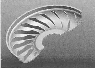
An open impeller is a type of centrifugal impeller with vanes that are not covered by a shroud. In other words, the impeller’s blades are exposed to the liquid being pumped. This design is typically used for low-pressure applications where the pumped fluid contains suspended solids or fibers (such as waste water or pulp), as the open impeller is less susceptible to clogging or damage than a shrouded impeller. The open design also makes it easier to inspect and clean the impeller. However, open impellers are less efficient than shrouded impellers due to increased turbulence and leakage around the vanes.

Semi-open impeller

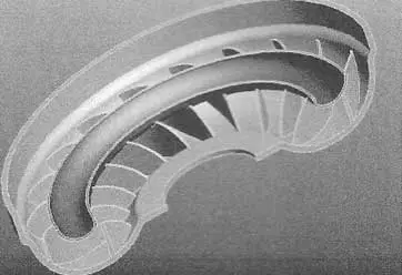
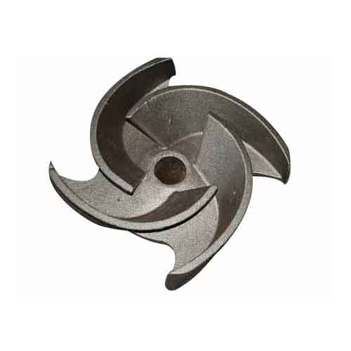
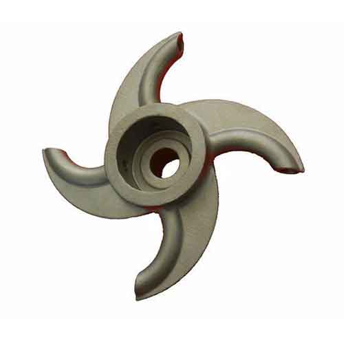
A semi-open impeller is a type of centrifugal pump impeller that has vanes on one side, leaving the other side open to the suction side of the pump. The fluid being pumped enters the impeller through the open side, and the vanes on the other side direct the flow outward to generate pressure and create flow. This design allows for the passage of solids and other debris through the pump without clogging, making it ideal for applications that involve fluids with high levels of solids or other particulate matter.

Closed impeller

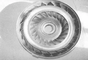
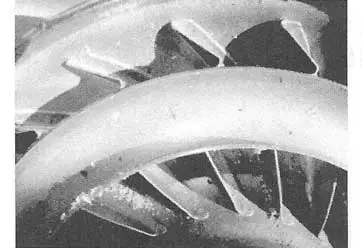
A closed impeller is a type of impeller used in centrifugal pumps. It consists of a circular plate with curved blades mounted on it. The blades are arranged in such a way that they form a completely enclosed chamber, with no space between them. This design allows the fluid to be pumped efficiently with minimal losses due to turbulence and backflow. Closed impellers are used in high-pressure and high-volume applications where the fluid being pumped is clean and free of abrasive particles. They are also used in applications where the fluid contains small or fine particles that could clog an open impeller.

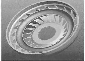
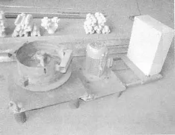
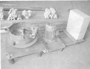
How to make impeller with investment casting?

Bellow video shows how investment casting impeller making.

  1. Design the Impeller: First, design the impeller to be cast with precision and accuracy, with important features like its size, shape, and the number of blades.
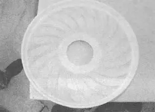
  1. Create a Mold Pattern: Create a mold pattern made of wax or plastic that will be the exact replica of the impeller. This will be used to create the investment mold.
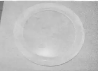
  1. Coat the Mold Pattern in Ceramic: Dip the mold pattern into a liquid ceramic slurry and dry it. Repeat this process several times, each time increasing the thickness of the ceramic coating.
  1. Burn Out the Wax: Once the final ceramic coating has dried, place the mold in a kiln to burn out the wax and any other impurities, leaving a hollow ceramic mold.
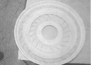
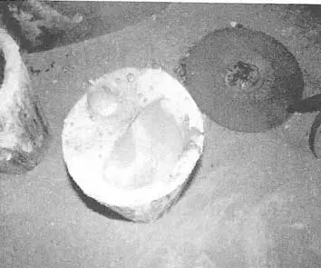
  1. Pour the Molten Metal: Once the mold is cleaned and prepared, pour molten metal into it. Allow to cool and solidify.
  1. Break the Mold: After the metal has cooled and solidified, break the ceramic mold to reveal the investment cast impeller.
  1. Finish the Impeller: Remove any excess material and finish the impeller to the desired shape and surface finish.
  2. Quality Check: The final step is to inspect the impeller for any defects and ensure it meets the required specifications.

Commonly used stainless steel for investment casting impeller

  1. AISI 316 – This stainless steel grade is known for its excellent resistance to corrosion and high-temperature resistance. It is commonly used in marine applications and in the chemical processing industry.
  2. AISI 304 – This is another commonly used stainless steel grade for impeller casting. It is known for its good corrosion resistance, weldability, and forming properties.

Chapter 1

Process Control of Impeller Investment Casting Productions

The structural characteristics of the impeller casting include a significant difference between the thickness of the casing and the thickness of the blades. The blades are not only numerous but also thin-walled, and they are connected to a semi-circular ring. Therefore, the casting of the impeller presents great difficulty. During the trial production of the impeller, the quality of the castings produced under non-vacuum melting and non-vacuum pouring conditions met the customer’s requirements, thanks to the control of process details.

The impeller has the following structural features: the casing has a significant difference in wall thickness compared to the blade wall thickness. The impeller casing contains 21 curved blades with a thickness of 1mm. Particularly, a semi-circular ring is connected to the blades, with a wall thickness of 1.6mm. The outer diameter of the casing is 270mm, the inner diameter of the ring is 230mm, the height is 62mm, and the weight of the casting is 2.3kg.

stamping and welding impeller

Figure 2-41 stamping and welding impeller

part view of stamping and welding impeller

Figure 2-42 part view of stamping and welding impeller

the impeller section where the blade matches the semicircle ring

Figure 2-43 the impeller section 3D view

Figure 2-41 shows the impeller after stamping and welding, while Figure 2-42 depicts the local condition of the stamped and welded blades. The outer shell of the impeller is made of 4mm steel plate, which is stamped and then welded to form the shape. The blades of the impeller are made of 1mm thin steel plate, which is stamped and then welded to the inner cavity of the shell. The semi-circular ring is also a stamped component that needs to be welded to the 21 blades. It is evident that using the method of assembling welded stamped components not only requires a large amount of work and has a long production cycle with low efficiency but also cannot meet the design performance requirements of the impeller or achieve the desired operating parameters. Therefore, it is necessary to modify the manufacturing method of the impeller to investment casting.

The state of the blades in the inner cavity of the casing

Figure 2-44 The state of the blades in the inner cavity of the casing

the position of the semi circular ring buried in the blade

Figure 2-45 the position of the semi circular ring buried in the blade

1.1- Control of process details

1.1.1-Mold Design

 From the shape of the impeller, the difficulty of investment casting lies in the inner cavity where the curved blades are connected to the semi-circular ring. There is an issue with demolding when attempting to produce a wax mold in one single pressing. Therefore, it is necessary to create two separate molds, press two wax molds, and then assemble them together. Refer to Figure 2-43 to Figure 2-45.

impeller blade wax mold

Figure 2-46 impeller blade wax mold

impeller semi circular ring wax mold

Figure 2-47 impeller semi circular ring wax mold

adhesive impeller wax mold

Figure 2-48 adhesive impeller wax mold

1.1.2-Mold preparation

  • a. Set up three stages of wax liquid filtration. For the low-temperature mold material, a hot water dewaxing process is adopted. Before the wax liquid flows into the treatment tank from the dewaxing tank, it undergoes the first filtration. After acid treatment, the wax liquid flows into the static settling tank for the second filtration. Before pouring into the mold frame, the wax liquid undergoes the third filtration.
  • b. Introduce a wax creation process. A cylindrical ingot with a diameter of 450mm and a length of 800mm is used. It is placed on the wax creation machine to be processed into thin wax slices. The wax paste is stirred quickly, evenly, and delicately to prevent any particles in the wax paste.
  • c. Cooling of the impeller wax molds. Strictly control the temperature of the mold-making room at 25°C. After removing the blade impeller wax mold and the circular ring impeller wax mold from the mold frame, do not cool them in water. Instead, store them in pairs on a flat surface. The impeller wax molds should not be stacked. After 2 hours, the molds can be repaired, and after 3 hours, the wax molds can be joined together using a connecting wax.
  • d. Assembly of the impeller wax molds. Discard the traditional chromium-iron welding process and use adhesive wax. Refer to Figure 2-46 and Figure 2-47. The heating temperature for the adhesive wax is generally 60°C. At this temperature, the adhesive wax liquid is relatively viscous, and a “wax pile” often appears on the bonding surface when bonding the impeller wax molds.

Therefore, raise the heating temperature to 70°C. Dip the semi-circular ring impeller wax mold in the adhesive wax liquid for less than 2 seconds. After dipping, do not immediately bond it. Use a brush to evenly coat the wax liquid, pause for 5-7 seconds, and then smoothly place the semi-circular ring impeller wax mold into the blade impeller wax mold, as shown in Figure 2-48.

Impeller spherical die head

Figure 2-49 Impeller spherical die head

exhaust strip Impeller spherical die head

Figure 2-50 exhaust strip Impeller spherical die head

horizontal sprue and semi circular ring connection

Figure 2-51 horizontal sprue and semi-circular ring connection

Integrated internal pouring channel

Figure 2-52 Integrated internal pouring channel

1.1.3-Design of Impeller Pouring System.

The design scheme of the first pouring and shrinkage system is to use a spherical riser and centrifugal pouring, following the requirements of the radius of the riser action zone, as shown in Figures 2-49 and 2-50.

Three thicker shrinkage gates are installed on the spherical riser to facilitate wax removal, exhaust, shell shrinkage, and improve the shell making rigidity of the module. The design scheme of the second type of pouring and shrinkage system involves centrifugal pouring with a spherical riser and a four forked inner runner, as shown in Figure 2-51.

four forked internal sprue

Figure2-53 four forked internal sprue

The design scheme of the third type of pouring and shrinkage system adopts an integral inner gate, with a complete circle of inner gate body set at the top of the impeller shell, 5 steel liquid channels set at the top, and a similar horizontal gate on top. Considering the characteristics of centrifugal casting, it is made into a whole circular shape, with a gate cup at the top, as shown in Figure 2-52..

In order to ensure the complete filling of the semi-circular ring in the inner cavity of the impeller and form a filling mode that combines the inner and outer parts, a straight sprue is introduced at the center of the lower end of the circular transverse sprue, which is connected to the inner wall of the through hole with a diameter of 74mm using a four pronged internal sprue, as shown in Figure 2-53.

1.2-Shell making process

1.2.1-Experimental process.

First layer: Apply mullite powder slurry for 35 seconds, sprinkle 80-100 mesh mullite sand, dry for 10 hours, with a drying room temperature of 23 ℃ and a relative humidity of 65%.
Second layer: Apply mullite powder slurry for 22 seconds, sprinkle 60-80 mesh mullite sand, dry for 12 hours, with a drying room temperature of 23 ℃ and a relative humidity of 65%.
Third layer: Apply mullite powder slurry for 15 seconds, sprinkle 60-80 mesh mullite sand, dry for 12 hours, with a drying room temperature of 23 ℃ and relative humidity of 50%. Blow air and tie iron wire.
Fourth layer: Apply mullite powder slurry for 14 seconds, sprinkle 30-60 mesh mullite sand, dry for 12 hours, with a drying room temperature of 23 ℃ and relative humidity of 50%, and blow air.
The fifth and sixth layers: apply mullite powder slurry for 14 seconds, sprinkle 16-30 mesh mullite sand, dry for 12 hours, with a drying room temperature of 23 ℃ and a relative humidity of 50%, and blow air. Sealing: Apply mullite powder slurry for 14 seconds, dry for 16 hours, dry at a temperature of 23 ° C and a relative humidity of 50%, and blow air.

Figure 2 54 about to be poured after baking

Figure 2-54 about to be poured after baking

Figure 2 55 Self made speed adjustable centrifuge

Figure 2-55 Self made speed adjustable centrifuge

1.2.2-Current production process

For the convenience of sand cleaning, the first and second layers remain unchanged. Before applying the third layer, the inner cavity of the blade is filled with sand (60-80 mesh sand) for sealing (in the future, powder will be added to form a mud like seal), and then the third, fourth, and fifth layers and sealing layers are made. The difficulty of cleaning significantly improves after pouring.
c. Module Dewaxing:
After dewaxing is completed, take out the Impeller shell and immediately rinse it twice with boiling water to thoroughly remove any remaining wax and debris inside the shell.

1.3-Roasting of the mold shell

a. Pre calcination: Place the mold shell into a calcination furnace and pre calcine at 950C. After the pre baked mold shell is cooled, clean the inner cavity of the mold shell with water.

b. Boxing roasting is the process of placing pre roasted Impeller mold shells into a circular iron box. The surface of the box filled with coarse sand is coated with a thin layer of silica sol, with the aim of evenly heating the Impeller mold shell and ensuring an increase in casting temperature for centrifugal casting, as shown in Figure 2-54.
c. The roasting temperature and insulation time of the Impeller shell are set at 1100-1150C, the insulation temperature of the mold shell is 1100-1150C, and the insulation time of the mold shell is>30min.

1.4-Melting and pouring

a. Self made centrifuge, trial production practice has proven that the impeller must use centrifugal casting in order to achieve complete filling. A self-made centrifugal machine with adjustable speed is shown in Figure 2-55.

b. Melting temperature and pouring temperature: High power furnace is used to melt all the furnace materials, and then heated to 1560-1570 ℃. Preheated manganese iron with a mass fraction of 0.20% and silicon iron with a mass fraction of 0.10% are added as pre deoxidizers to remove the slag, cover the slag remover, remove the slag, and add pure aluminum with a mass fraction of 0.03% for deoxidation, steel quenching, and slag removal. The material of the impeller is ZG310-570, and the tapping temperature is generally 1570-1590 ℃. Considering the complete filling of the impeller, the tapping temperature is increased to 1610-1620 ℃.

c. Pouring speed and centrifuge speed: According to the formula of centrifugal force F ‘=0.112R, (n/100) 2, and gravity coefficient G=0.112 (n/100) 2R, after calculation and production practice, the centrifuge speed is set to 293r/min, and the pouring time is controlled within 5-8s. When the molten steel is poured close to the riser neck, it immediately stops rotating.
d. Pouring and Baking of Pouring Bags: Homemade 10kg teapot small pouring bags, which are naturally dried for more than 1 day after being poured. When the mold shell is pre baked, the pouring bags are also pre baked. When the impeller casting mold shell is packed and baked, it needs to be baked again in the furnace at the same time.

Figure 2 56 Baked 10kg teapot bag

Figure 2-56 Baked 10kg teapot bag

When pouring, it should be taken out of the furnace together with the impeller casting mold shell. In order to minimize the decrease in pouring temperature of the steel liquid, after pouring the steel liquid into the tea shell package, immediately return the steel liquid to the furnace. After pouring the steel liquid into the tea pot package for the second time, pour it immediately. The teapot bag is shown in Figure 2-56.

Strict control: Pour one set of Impeller casting shells per pot.
Strict control: If there is any remaining steel liquid in the ladle, it must be poured back into the furnace.

Three thicker shrinkage gates are installed on the riser to facilitate wax removal, exhaust, shell shrinkage, and improve the shell making rigidity of the module.


e. Clear division of labor and coordinated cooperation: The three processes of roasting, smelting, and pouring are the key to producing impeller casting. In addition to strictly adhering to the process regulations, on-site production emphasizes unified command, close cooperation, and collaborative operation.

f. Insulation cooling to prevent cracking. Strictly limit the unboxing time, allowing the just poured castings to slowly cool in the iron box. At room temperature of 30 ℃, remove the casting impeller from the iron box 3 hours after pouring (if the unboxing time is also delayed in winter), and continue to cool naturally at room temperature until the mold shell is touched by hand without feeling hot, before vibration and peeling can be carried out. This can effectively prevent cracks from occurring, and water cooling should be avoided throughout the entire cooling process.

Figure 2 57 Castings Poured from a Spherical Riser Pouring System

Figure 2-57 Castings Poured from a Spherical Riser Pouring System

Figure 2 58 Castings Poured out by the Integrated Internal Gate Pouring System

Figure 2-58 Castings Poured out by the Integrated Internal Gate Pouring System

g. Civilized cleaning and standardized operation. During the process of removing the shell on the casting impeller, cutting off the sprue and process ribs, and removing the sand and oxide scale inside the casting cavity, it is necessary to handle it gently, stack it neatly, prevent damage to the blades, adhere to civilized cleaning, and operate in a standardized manner. Using a tracked shot blasting cleaning machine, the particle size of the shot blasting should not exceed 0.3mm. For residual coatings that are difficult to remove at the inner groove, they should be soaked in a slag removal solution.

The casting results are achieved by strengthening the control of process details in each process of investment casting, and producing high difficulty and high requirements Impeller casting under non vacuum melting and non vacuum pouring conditions. It is reported that Japan still uses stamping and welding processes to produce the same type of impeller casting.
Under the same process control conditions, for the integrity of filling, the overall internal sprue gating system is superior to the spherical riser and transverse sprue gating system, as shown in Figures 2-57 and 2-58.

Commonly used stainless steel for investment casting impeller

Impeller investment casting is a casting process that involves producing complex impeller shapes through the use of a wax pattern and a ceramic shell. The wax pattern is created using an injection molding process, after which it is coated in a ceramic shell. The shell is then heated to remove the wax pattern, leaving a cavity that is filled with molten metal to produce the final impeller shape.

 Impeller investment casting is commonly used in industries such as aerospace, marine, and power generation, where high-performance impellers are required to withstand extreme operating conditions.

When selecting an impeller investment casting supplier, it is important to consider factors such as their experience and expertise with the casting process, their quality control processes, their ability to produce complex geometries with high accuracy, and their lead times and pricing.

Impeller investment casting offers several benefits, including the ability to produce complex geometries with high accuracy and repeatability, the ability to use a wide range of materials, and a high level of surface finish.

A wide range of materials can be used in impeller investment casting, including stainless steel, titanium, and aluminum alloys.

Impeller investment casting can be limited by the size and complexity of the impeller, as more complex geometries may require larger, more expensive equipment. Additionally, impeller investment casting can be more expensive than other casting processes, making it less economically viable for smaller-scale production runs.