As a professional valve casting manufacturer and supplier based in China, Chongqing Sipx Machinery specializes in producing high-quality valve components through advanced casting techniques. Our valve casting process involves pouring molten metal into precision molds to create durable valve bodies, discs, and stems with exact specifications.
The valve casting manufacturing service is essential for producing reliable components that meet the demanding requirements of various industries, including oil and gas, chemical processing, water treatment, and power generation. Utilizing our foundry expertise, we create valve parts capable of withstanding extreme pressures, corrosive environments, and high-temperature conditions while ensuring long-term performance.
With years of experience in valve casting production, our China-based foundry combines traditional craftsmanship with modern technology to deliver components that exceed industry standards for durability and precision.
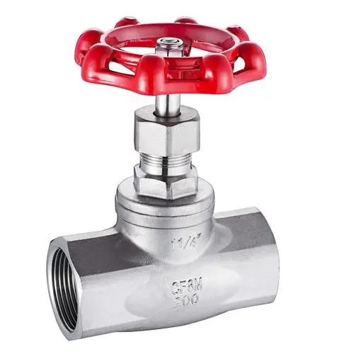
stainless casting valve
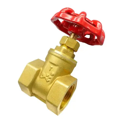
brass casting valve
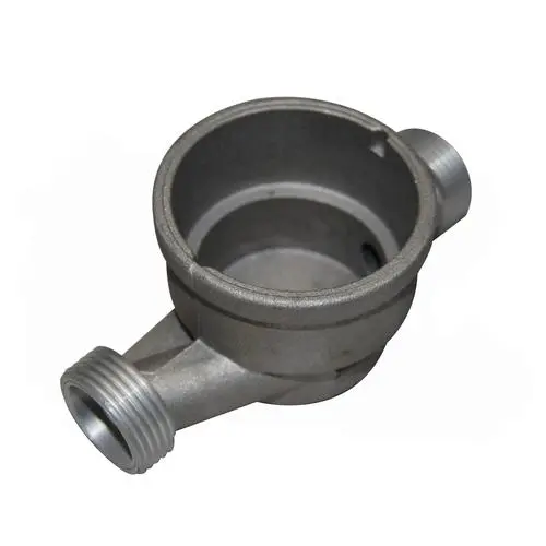
casting valve meter part

red paint casting valve
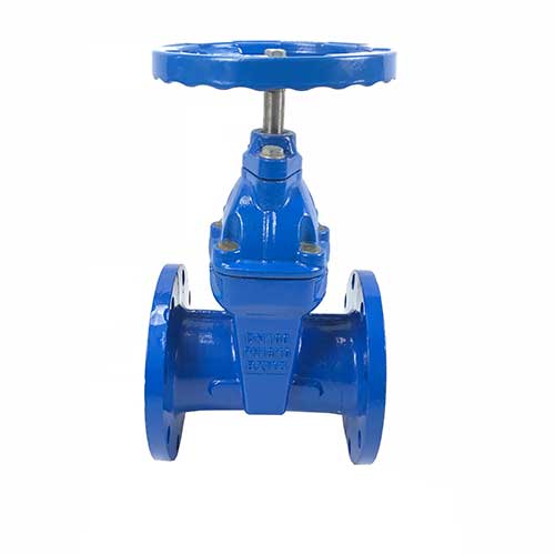
casting valve with blue paint
stainless valve casting parts
Valve Casting Methods: Advanced Techniques by a Leading China Manufacturer
As a trusted valve casting supplier and foundry in China, Chongqing Sipx Machinery employs six proven casting methods to deliver precision-engineered valve components. Below are the valve casting processes we specialize in:
-
Sand Casting
The most widely used valve casting method globally, sand casting creates molds from bonded sand. Our foundry pours molten metal into these molds to produce robust valve bodies, discs, and stems ideal for high-temperature industrial applications. -
Perfect for complex valve geometries, this method uses wax patterns coated in ceramic shells. As a professional valve casting manufacturer, we melt the wax and inject molten metal to achieve exceptional surface finishes and tight tolerances.
-
Die Casting
Our high-pressure die casting service forces molten metal into reusable steel molds, ensuring mass production of uniform valve components with minimal post-processing. -
Lost Foam Casting
This innovative valve casting technique uses evaporative foam patterns to create near-net-shape valve parts, reducing material waste and machining costs – a specialty of our China-based foundry. -
Continuous Casting
For large-scale valve component production, we utilize continuous casting to form elongated metal profiles that are precision-cut to meet client specifications. -
Gravity die casting
Combining excellent dimensional accuracy with smooth surface finishes, this method is ideal for aluminum and zinc alloy valves requiring intricate designs.
As an ISO-certified valve casting supplier in China, Chongqing Sipx Machinery selects the optimal casting method based on your component design, production volume, and performance requirements. Our valve casting services balance cost-efficiency with unmatched durability for oil/gas, chemical, and power generation industries.
Types of materials used for valve casting
Valve casting requires materials with high strength, corrosion resistance, and good wear resistance. The selection of materials for valve casting depends on the application, operating conditions, and the fluid or gas being handled. Some of the commonly used materials for valve casting include:
|
Materials |
Detail |
|
Carbon Steel |
Carbon steel casting also called iron casting is a widely used material for valve casting due to its high strength, durability, and low cost. It is suitable for applications where the fluid or gas being handled is not corrosive. |
|
Stainless Steel |
Stainless steel is a popular choice for valve casting due to its excellent corrosion resistance, high strength, and durability. It is suitable for applications where the fluid or gas being handled is corrosive, such as in the chemical and petrochemical industries. |
|
Alloy Steel |
Alloy steel is a material that is used for valve casting in applications that require high strength and corrosion resistance. It contains other elements such as chromium, nickel, and molybdenum to improve its properties. |
|
Brass and Bronze |
Brass and bronze are copper-based alloys that are used for valve casting due to their excellent corrosion resistance, low friction, and good wear resistance. They are suitable for applications that involve water, steam, and other non-corrosive fluids. |
Post processes after valve casting
As a professional manufacturer and supplier from China, we are committed to providing top – notch valve casting services. After valve casting, several crucial post – processes are often required to achieve the desired final product. These include:
-
Machining: Machining is a vital process for valve casting. It involves removing excess material from the casting to attain the desired shape and dimensions. We utilize advanced tools like lathes, milling machines, and grinders to ensure precision machining of your valve castings. Our skilled technicians operate these machines with expertise to deliver castings that meet tight tolerances and exact specifications.
Heat Treatment: Heat treatment is another essential post – process for valve casting. This process involves heating the casting to a specific temperature and then cooling it at a controlled rate. At our foundry in China, we have state – of – the – art heat treatment equipment and experienced personnel to optimize the mechanical properties of your valve castings. We can enhance the strength, hardness, and durability of your castings to meet the demanding requirements of various applications.
Surface Treatment: Surface treatment plays a significant role in improving the performance and appearance of valve castings. We offer a variety of surface treatment options, including painting, plating, powder coating, and more. These treatments can enhance the corrosion resistance, wear resistance, and aesthetic appeal of your valve castings. Our surface treatment services are tailored to meet the specific needs of your application and industry standards.
Assembly: After completing machining, heat treatment, and surface treatment, the valve casting may need to be assembled with other components to create the final valve product. Our experienced assembly team in China can handle this process efficiently and accurately. We ensure that all components are properly aligned and secured, guaranteeing the functionality and reliability of the final valve assembly.
Each of these post – processes is indispensable in achieving the desired final product and ensuring that the valve casting meets the specific requirements of the application. At Chongqing Sipx Machinery, we understand that the choice of post – processes depends on the particular needs of the valve casting and the demands of the application. Our comprehensive post – processing services are designed to add value to your valve castings and deliver products that perform reliably in their intended environments.
Different industries that use valve castings
Valve casting, as a crucial manufacturing process, produces valve components that are widely used across various industries. Below are some common applications:
- Oil and Gas Industry: As a professional valve casting manufacturer and supplier from China, we produce valves that control the flow of oil and gas in pipelines, refineries, and petrochemical plants. Our valve castings are specifically designed to withstand high pressure, high temperature, and corrosive environments, ensuring reliable performance in this demanding industry.
- Power Generation: Our China – based foundry provides valve casting services for power plants. The valves we produce are capable of controlling the flow of steam and water, designed to endure high temperature and pressure while preventing leaks and failures, which is essential for the safe and efficient operation of power generation facilities.
- Chemical and Petrochemical Industry: We offer high – quality valve casting services for chemical and petrochemical processing plants. Our valve castings can handle corrosive and abrasive fluids and are built to withstand high temperature and pressure, meeting the strict requirements of this industry for material compatibility and durability.
- Water Treatment: Our valve casting products are used in water treatment plants to control the flow of water and chemicals. The valves are constructed to handle corrosive and abrasive fluids, ensuring long – term functionality and minimal maintenance in water treatment applications.
- Aerospace Industry: We provide precision valve casting services for the aerospace sector. The valves we produce for aircraft engines and hydraulic systems are engineered to withstand high temperature, high pressure, and harsh environments, meeting the exacting standards required for aerospace components.
- Marine Industry: Our valve castings are utilized in marine applications such as shipbuilding, offshore drilling, and oil platforms. They are designed to withstand corrosive seawater and harsh marine environments, providing reliable performance in naval and offshore operations.
In summary, valve casting from Chongqing Sipx Machinery is a versatile manufacturing process that produces valve components used in various industries. These industries demand high – performance and reliability in severe – service applications. As a trusted China foundry and supplier, we are committed to delivering valve casting services that meet the specific needs of each industry, ensuring that our products perform effectively in their intended environments.
Chapter 1
Valve Precision Casting Molding System Design Practice
This section introduces targeted process measures taken in the design of the casting and feeding system for valve castings based on their structural and usage characteristics, with the aim of reducing defects such as looseness and shrinkage holes and improving the internal quality of the castings. Different casting system design schemes and empirical formulas for determining the dimensions of each part of the casting system are proposed based on the structural and dimensional characteristics of butterfly valve bodies, ball valve bodies, and gate valve bodies.
Valve castings must undergo pressure testing, and the requirements for their working and usage states determine that they cannot have looseness or shrinkage holes and must have good compactness. Therefore, the rationality of the casting and feeding system design is crucial.
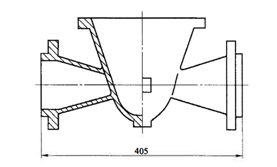
1.1 Feeding and Shrinkage Form of Butterfly Valve Body
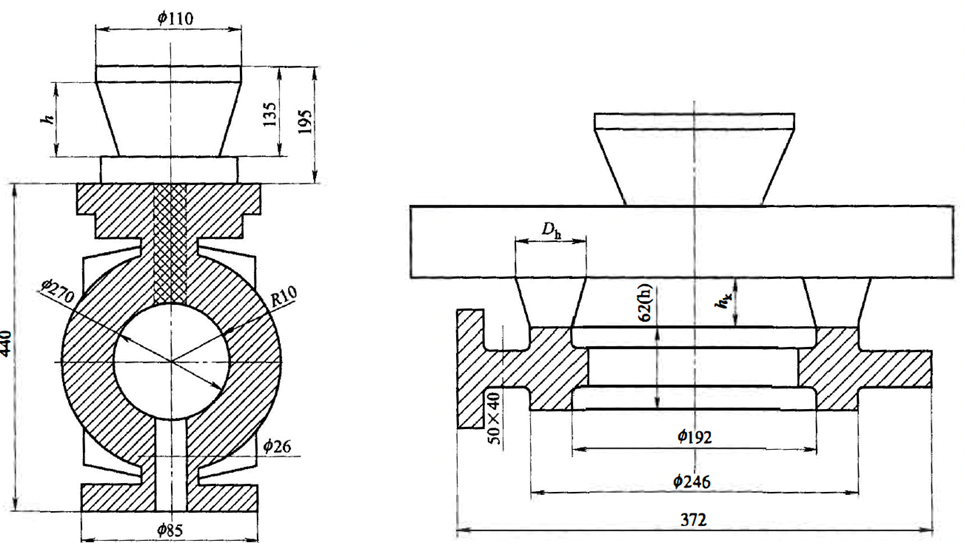
Figure-6-11:Valve wax mold diagram
The process parameters are as follows:
Inner gating thickness: h2=1.2D1=l.2X25=30mm
Inner gatin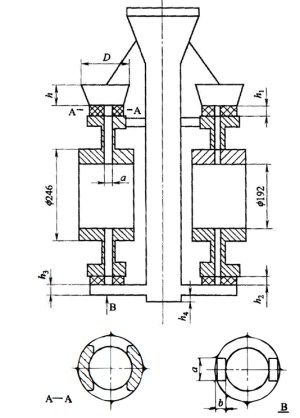 g width: b=h2
Transverse gating length: 115mm
Transverse gating thickness: h3=2/3h2
Riser height: h4=15mm
Sprue diameter: D=2.5D1=62.5mm
Sprue cone angle: 15°
Sprue neck height: h1=D1
Sprue height: h=3D1=75mm
The shape of the sprue neck is shown in Figure 6-13 A-A section.
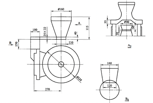
1.2 Gating and feeding system for large-scale ball valve body casting
Casting Methods and Design Principles
Avoiding Horizontal Pouring
Flange Components and Casting Method
Addressing Neck and Small Flange Feeding and Shrinking
Shrinkage Cavities in Valve Bodies with Protrusions
Calculation of Sprue Diameter and Height
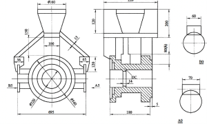
Figure 6-14 Ball valve body wax mold
D=(2.2~ 2. 5)Dc
h=(3~ 3.S )Dc
Design a hidden riser with dimensions of 80mm X 60mm X 60mm. It is welded to the lower part of the thermal node and connected to the bottom plane of the transverse gating system. This form is adopted to eliminate shrinkage cavities and shrinkage defects in the casting.
The dimensions of the inner gating connecting the flange bodies for such castings are determined based on production experience. If the flange diameter is greater than 500mm, the width of the inner gating is 1/6 to 1/5 of the flange diameter, and the height of the inner gating is 1/3 to 1/4 of the flange diameter. If the flange diameter is less than 200mm, the width of the inner gating is 1.5/5 to 2/5 of the flange diameter, and the height of the inner gating is 1/4 to 1/5 of the flange diameter.
1.3 Pouring and shrinking system of gate valve body
Transverse Gating System Design
Hidden Riser Design for Wall Thickness Adjustment
Application in Valve Cover Casting
1.4 Comparison of two valve plate feeding and solidification methods.
The gate plate assembly schemes can be seen in Figure 6-17 and Figure 6-18, with the same shape and dimensions. Only the feeding and solidification methods differ between the two. The feeding and solidification effect in Figure 6-17 is better than that in Figure 6-18.
1.5 Design and calculation of risers
(a)Sluice Valve body
(b) Sluice valve bod wax mold
Figure 6-15: Sluice valve body
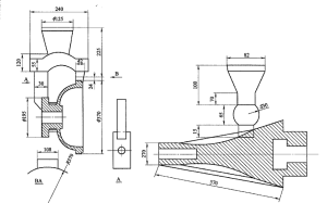
Figure 6-16: Sluice valve body casting cover
Formation mechanism and solutions for shrinkage and porosity. The formation process of shrinkage and porosity is mainly affected by the heat absorption of the mold shell and the temperature difference with the outside world when the liquid metal fills the mold cavity. A hard shell solidifies on the surface of the casting and tightly encloses the liquid metal inside. With further cooling, the hard shell becomes thicker and the liquid level follows to generate liquid and solidification.
As a result, a cone-shaped shrinkage and an axial porosity are formed at the thermal section, central area, and upper part. A complete gating and riser design system must be equipped around this area. To set up a reasonable gating and riser system, we should first start from the end area of the casting, determine the direction of sequential solidification, analyze the filling and non-filling areas, and then decide the position of the gating and riser. At the same time, the size of the gating and riser should be calculated according to the modulus method, and necessary allowances should be added if needed.
The compensation distance of the riser is the sum of the dense riser area and the dense end. The determination methods for the compensation distance include flat shape, square shape, step-shaped cocoon shape, circular shape, upright shape, etc., as shown in Figure 6-19 to Figure 6-21.
The modulus calculation method establishes a proportional relationship between the length of solidification and the volume V and surface area S of the casting. That is, Ma = VIS (mm), and this ratio Ma is called the solidification modulus of the casting. In process design, the modulus of the riser must be greater than the modulus of the casting at the compensating shrinkage section to ensure smooth supply of liquid metal from the riser to the casting. Considering fluid mechanics and physical chemistry theories, the ratio K between the riser modulus M_riser and the casting modulus M_casting should be greater than 1.3 to achieve better results.
The formulas for calculating the casting modulus can be found in Table 6-2. The constant proportion relationship among the casting modulus M_casting, the inner gate (riser neck) modulus M_inner, and the riser modulus M_riser is: M_casting : M_inner : M_riser = 1:1.2:1.3. In the case of high mechanical performance requirements, the proportion relationship is: M_casting : M_inner : M_riser = 1:1.3:1.5. By using the formulas, suitable dimensions for the riser and riser neck can be obtained from Table 6-3 and Table 6-4.
FAQ

Valve casting is the process of creating valves by pouring molten metal into a mold and allowing it to cool and solidify into the desired shape.
The most common materials used in valve casting are stainless steel, carbon steel, and alloys like bronze and brass.
Valve casting offers several advantages, including the ability to create complex shapes and designs, high precision and accuracy, durability, and the ability to produce large quantities of valves efficiently.
We make precision casting parts according to clients drawings or samples. Faucets fittings, valve settings, automotive spare parts are common made in our foundry.
We used stainless steel 304,304L,316,316L,410,416 and 17-4.
The most common types of valve casting are sand casting, investment casting, and die casting.
Valve casting is used in a variety of industries, including oil and gas, chemical processing, power generation, and water treatment.
The production capacity of our precision casting foundry can produce 50000pcs per month.
The process of valve casting involves creating a mold, melting the metal, pouring it into the mold, allowing it to cool and solidify, removing the mold, and finishing the valve with machining, polishing, and other processes.

At SipxMach, our goal is to help our customers lower production costs and increase production rates and quality. Interested to see what SipxMach can do for you and your team? Contact us to schedule a tour of our state-of-the-art facility
- Contact: Rubio
- Email: [email protected]
- Microsoft Teams: Rubioli8677 (Sales manager)
- Office Add: No.551, Baosheng Avenue, Huixing Street, Yubei District, Chongqing, China
- Foundry Add: No. 4 Jindi Avenue, Dongcheng Street, Tongliang District, Chongqing